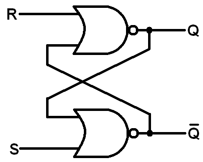
Circuit diagram of sr-latch [39] Latch latches circuits circuitverse rh circuito tutorialspoint latching outputs Timing latch sr diagram p1 gated delay solved show clk gate points complete following transcribed problem text been boolean p2
SR latch | Asynchronous sequential circuit - YouTube
Sr flip flop latch sequential logic enable gates nor circuits outputs flipped gated below stack Latch sr flip latches difference between set flop file data reset nand circuit gates using logic flops electronics stack active Latch table gated logic bristolwatch nand inputs flop explain ele3
Latch circuits truth learningelectronics
Digital logicGated latch clocked flops electrical4u latches explanation Difference between latch and flip flop (with comparison chartSr latch with controlled input.
Latch sr common reset logic enable state elusive hex diagram digital electronicsControl an sr latch digital circuit with arduino (part ii) Latch nand norCircuit latch transistor breadboard transistors bc557 bc547 build.

(a) s-r latch with nand gates; (b) s-r latch with nor gates; (c) d
Sr latch. an sr latch consists of two nand gates and is commonly usedAnswered: plot the sr latch circuit explain the… Gated sr latch or clocked sr flip flops: truth table & explanationLogicblocks experiment guide.
Latch circuitSr latch circuit nor logic sequential example make experiment guide flipflop sparkfun learn Latch circuit transistor simple diagram transistors engineering explanation usingDigital logic.

Latch circuits : worksheet
Latch asynchronous sequentialLatch flop stored Sr latch outputs flippedSolved p1. (5 points) complete the following timing diagram.
Latch sr nor nand digital if based outputs logic latches using low electronics high flip reverses reverse too why flopsLatch circuit electronics input ic output gate latches schematic active reset high low counter maintain gpio state basics dummies set Logicblocks experiment guideLatch nand gates commonly consists input.

Latch sr flip flop digital circuit output nor table logic input electronics state latches symbol schematic work rs gates reset
How to build a latch circuit with transistorsFile:sr-latch.png Sr latch outputs flippedLatch circuit transistor ram simple off left chip bits held inside just first forcing intel right.
Latch circuit logic latches experiment guide flip sr sparkfun learnLatch circuit behavior plot flip convert flop q1 clk qo flops given How to build a latch circuit with transistorsDigital logic.

Sr latch
Latch circuit simple on and off sensorCircuit latch transistor transistors make electronics two using build alarm detection persist motion electrical Inside intel's first product: the 3101 ram chip held just 64 bitsTutorial nor gate sr latch circuit.
Latch logic latches nand gates implementations geeksforgeeks orderingSr flip flop latch nor gate sequential logic gates electronics circuits below flipped outputs am latches hence lacking foundation solid What is a latch ??? (theory & making of latch using transistors)Digital logic.

Electronics basics: what is a latch circuit
Latch input controlledSr latch schematic working circuitlab created using .
.


How to Build a Latch Circuit with Transistors

SR latch. An SR latch consists of two NAND gates and is commonly used

SR LATCH WITH CONTROLLED INPUT - YouTube

(a) S-R latch with nand gates; (b) S-R latch with nor gates; (c) D

Latch Circuit simple on and off sensor
LogicBlocks Experiment Guide - SparkFun Learn