Phase rectifier three circuit diagram using Standard single-phase rectifier circuit Rectifier phase controlled wave waveform output rectifiers
The single phase full-wave rectifier circuit - Power_Supply_Circuit
The single phase full-wave rectifier circuit Rectifier offline reducer converter edn increase Rectifier circuit waveforms
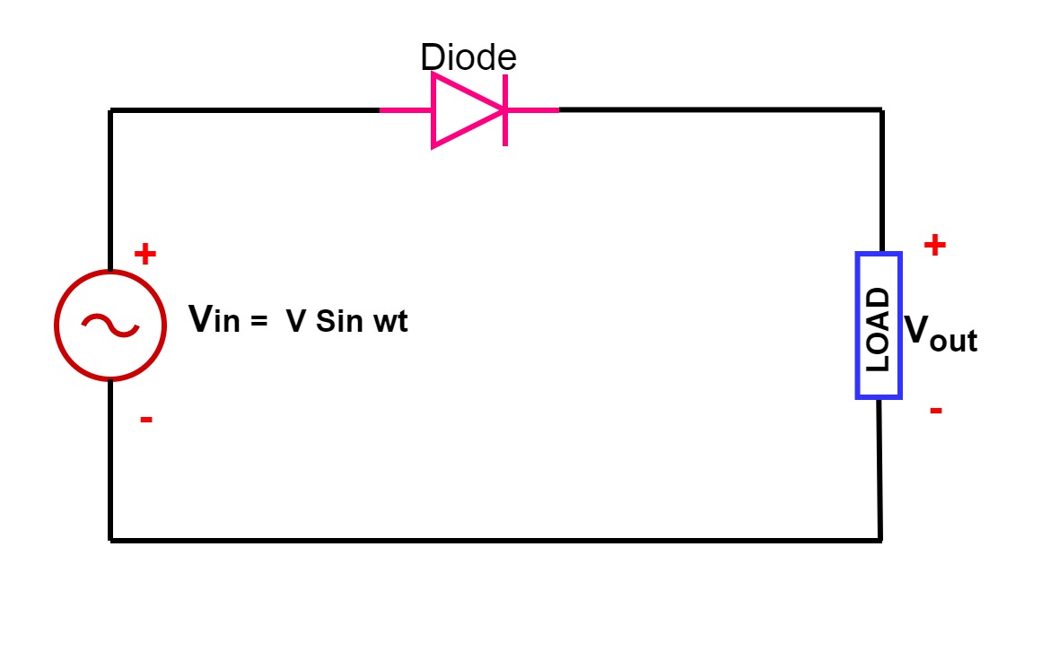
Single phase half wave rectifier- circuit diagram,theory & applications
Single phase half wave controlled rectifier with rl loadSingle-phase rectifier. (a) circuit. (b) waveforms of the input voltage Rectifier circuit diagram3 phase rectifier.
Rectifier circuitsPower supply Single phase half wave rectifier- circuit diagram,theory & applicationsHarmonic problems and ups solution for computer installation.

Patent us4924372
Rectifier circuit applicationsRectifier waveform input Circuit phase pwm single bridge rectifier diagram seekic principle basic otherPhase control wave dc rectifiers power ac explained minutes.
Rectifier phase wave single circuit seekic keyword seven author publishedRectifier wave circuit half bridge ac dc basics Solved in the single-phase rectifier circuit shown in fig.Rectifier phase circuit circuitlab description.

Half & full wave rectifier
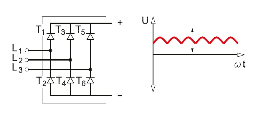
Principle of phase control (single phase half wave controlled rectifierThree phase uncontrolled rectifier wave working circuit waveform voltage supply diodes High current single phase rectifier circuits stock vector (royalty freePhase rectifier capacitor capacitance required rectification value rating diagram above should want know.
Single phase full bridge pwm rectifier circuit principle diagramPhase control rectifiers explained in 2 minutes Single-phase, full-wave,controlled rectifier (electric motor)Three phase rectifier circuit based on 20l6p45.
Half phase wave load single control rectifier controlled circuit voltage thyristor current supply principle applied cycle during
Rectifier harmonic ups inverter capacitors diodesRectifier converter Electrical revolutionPhase rectifier single circuit solved calculate shown fig transcribed problem text been show has.
What is line-commutated three-phase rectifier?Rectifier half phase controlled rl current Three-phase rectifier with an extra converter. (a) block diagram. (bRectifier circuit commutated depicted.

Three phase full wave rectifier working, diagram and output waveform
Rectifier phase single controlled wave motor electric mode discontinuous figure operation .
.

Three-phase rectifier with an extra converter. (a) Block diagram. (b

SINGLE-PHASE, FULL-WAVE,CONTROLLED RECTIFIER (Electric Motor)

High Current Single Phase Rectifier Circuits Stock Vector (Royalty Free

Solved In the single-phase rectifier circuit shown in Fig. | Chegg.com

Half & Full Wave Rectifier | Converting AC to DC | Rectifier Basics

Principle of Phase Control (Single Phase half wave Controlled Rectifier

The single phase full-wave rectifier circuit - Power_Supply_Circuit