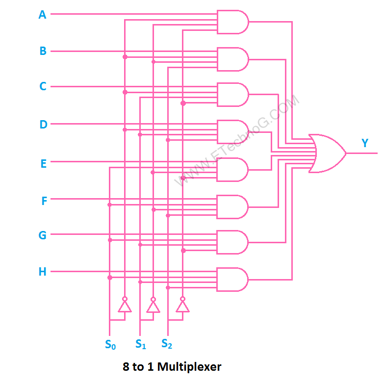
Mux diagram circuitverse 8x1 logic wiring combinational Mux part circuit hdl Multiplexer mux
4:1 MUX circuit - Multisim Live
Operational amplifier 4:1 mux circuit Multiplexer circuit truth table types applications input output uses
Verilog code for 2:1 multiplexer (mux)
A multiplexer schematic structure, b truth table of the mux based onMux using gates logic input circuit circuitlab electronics chain together questions them make Mux multiplexer 8x1 diagram mainetreasurechest unique sourceMux circuit circuitlab description.
2-to-1 mux using if-then-else statement in vhdl – buzztechMux circuit multisim 4 to 1 muxBlock diagram of the 2 : 1 mux with a ce circuit..

Mux using latch storage data schematic simple complicated sr instead circuit logic circuitlab created stack
Mux multiplexer verilog 2x1 code technobyteDigital logic Digital logicBlock diagram of the 2:1 mux ic..
4 x 1 mux using logic gatesMux 8x1 multiplexer schematic using input 16 vlsi symbol 2x1 muxes figure structure structural universe eda Mux multiplexer schematic structure inputs diagram consideringMux circuit.

Mux schematic figuring inputs circuitlab created using
Types of multiplexer applications, uses, circuit and truth table2x1 mux : vlsi n eda Chevrolet wiring diagram mux images8x1 mux unique.
8:1 mux : vlsi n edaWhat is a multiplexer? operation, types and applications Mux vhdl using diagram block else statement then ifNand2tetris part 1: boolean algebra and logic gates.

Multiplexer circuit demultiplexer multiplexers mux types gates using gate applications differences its their
Multiplexer and demultiplexer : types, differences & their applicationsMultiplexer mux input demultiplexer wiring Mux analog circuit amplifier analysis gain electrical operational2x1 mux logic schematic vlsi multiplexer inverter input.
Multiplexer diagram circuit block inputs operation output selection lines types applications needed shown below data8x1 mux logic diagram : solved using the following circuit diagram .


8X1 Mux Logic Diagram : Solved Using The Following Circuit Diagram

Block diagram of the 2:1 MUX IC. | Download Scientific Diagram

digital logic - design data storage using a simple MUX instead of a

a Multiplexer schematic structure, b truth table of the mux based on

Chevrolet Wiring Diagram Mux Images - Faceitsalon.com

Verilog code for 2:1 Multiplexer (MUX) - All modeling styles
4:1 MUX circuit - Multisim Live

2-to-1 MUX using if-then-else statement in VHDL – Buzztech